Difference is that transformer is an alternating flux machine while induction motor is rotating flux machine. This winding can be supplied with 3 phase ac supply.
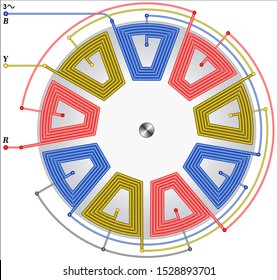
All the diagramsphotos ive seen show an individual winding in the shape of a rectangle with rounded corners.
You can find out more Diagram below
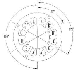
Motor stator winding diagram. Winding diagram count number of slots gaps in stator look at pictures. Current which is flows inside picture has clockwise direction of magnetic field. This video is perfect.
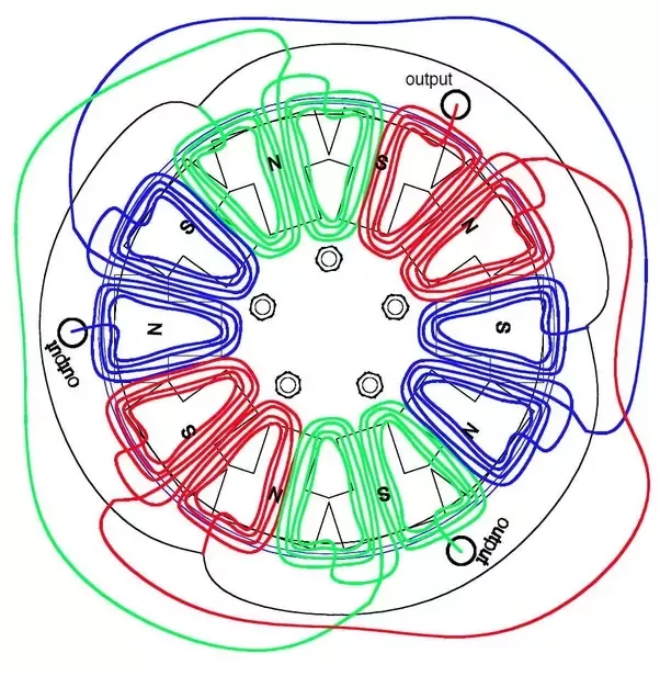
The motor winding in three phase which is connected in star or delta form based on the type of starting method used. Second picture is showing the magnetic field generated by stators winding. In this video i showed motor rewinding 36 slots 3 phase 6 pole with diagram.
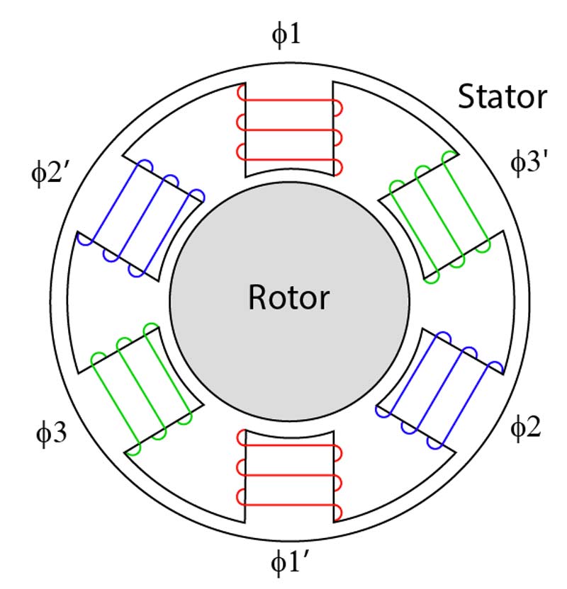
The slot on stator core of the three phase motor winding carries stator winding. In single phase induction motor we have two types of winding coils in stator. The connection for a 6 pole stator is shown in figure 11.
Induction motor is a generalized transformer. It show how stator coils are connected with each other. I remade winding diagram from book so it fits into my stator.
Terminal markings and internal wiring diagrams single phase and polyphase motors meeting nema standards b. I draw new winding diagram which i had used at winding motor. Rotating flux is only possible when 3 phase voltage or poly phase which is 120 degree apart in time is applied to a three phase winding or poly phase winding 120 degree apart in space then a three phase rotating magnetic flux is.
Inst maint wiringqxd 5032008 1002 am page 6. Winding diagram is diagram which helps you rewind motor. Type one the axis of the winding points toward the shaft of the rotor.
Single phase motor winding diagram main winding and starting winding. In which one is made from thick wire and 2nd is made from the thin wire. O and x are showing direction of electric current.
If a single phase motor is single voltage or if either winding is intended for only one voltage the terminal marking shall be determined as follows. Here i described and calculate all data. These diagrams are current at the time of publication check the wiring diagram supplied with the motor.
Ive looked at many diagrams and photoscutaways of stator wiring and ive noticed two different orientations for the windings. To produce a rotating magnetic field in the stator of a three phase ac motor all that needs to be done is wind the stator coils properly and connect the power supply leads correctly. Refer to the motor manufacturers data on the motor for wiring diagrams on standard frame ex e ex d etc.
For example one winding made from 21 swg standard wire gauge and 2nd is made from 26 swg. If you new and want to learn induction motor rewinding.


0 comments:
Post a Comment