The image above shows a single axle trailer and the next image shows wiring for tandem axles. Check out or trailer wiring diagrams for a quick reference on trailer wiring.
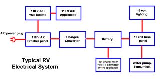
The diagram below shows a typical rv electrical system set up with a converter.
You can find out more Diagram below
Typical rv wiring diagram. This chart is a typical guide wire colors may vary based on manufacturers. Use a circuit tester to verify connections. You can use a circuit tester to verify connections.
Next before you plug in take a few safety precautions and switch everything off both your rvs electrical system and the rv electrical pedestal. Not to be rude if a person request a wiring diagram then that person should get said wiring diagram if its available. Typical trailer wiring diagram and schematic.
In fact that is probably an understatement. Honestly wiring diagram should be part of the instruction manuals for an rv because they get very limited shitty warranties and if you own anything made by keystone it is the biggest piece of garbage known in the rv world. Types of rv electricity there are 2 main types of sources of rv electricity within your rv 12 volt dc and 120 volt ac same as 110 volt just like your stick brick for our purposes.
Below is a rv electric wiring diagram or schematic including the converter and inverter for a generic rv. It reveals the parts of the circuit as streamlined shapes as well as the power and also signal links in between the gadgets. When this is the case the lockout should be connected.
The below information is for reference and is commonly used throughout the industry but can vary depending on who built the trailer. Extrapolate the same expansion for additional axles. Only the blue brake and white ground wires are different.
This chart is a typical guide wire colors may vary based on manufacturers. Now most electrical experts will agree that the converter that comes from the factory in most rvs while functional is not the best method for charging your house batteries. Trailer wiring diagrams trailer wiring connectors various connectors are available from four to seven pins that allow for the transfer of power for the lighting as well as auxiliary.
In fact it is a commonly available 50 amp 250 volt receptacle. 50 amp rv service can deliver approximately 12500 watts 125 volts x 50 amps x 2 to the rv. This is a relatively common and affordable tool that can be purchased for 40 or less and its a great insurance policy against inadvertent damage to your rv electrical wiring.
250 volt 50 amp ac wiring. The fifth connection is sometimes used on 5 ways to power a reverse lockout on trailers with surge brakes. Use a circuit tester to verify connections.
These 2 wire diagrams fit the needs for most trailers. Some people believe that the 50 amp rv receptacle is a special part. This is absolutely not true.
A wiring diagram is a streamlined traditional photographic depiction of an electric circuit.


0 comments:
Post a Comment